PCB Design
Custom PCB designs for embedded robotics systems - schematic capture, layout, and fabrication.
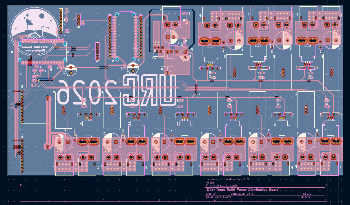
Team RoSE - Motor Control System Board
Jan 2026 - April 2026 · 2-Layer · KiCad 10 · Pink soldermask · JLCPCB
Professional-grade motor control PCB for the Team RoSE Mars Rover. Integrates nine independent 40A power monitoring blocks, dual stepper motor drivers, dual Arduino Nano ESP32 microcontrollers, Hall-effect current sensing, GPS, 9-axis IMU, and an OLED display into a single 2-layer board. Designed with strict EMI management, a unified GND plane strategy, and mixed high-current/signal routing on 2oz copper.
KiCad 10
40A Power
AMIS-30543
ACS758
ESP32
Stepper Control
Rover Avionics Motherboard
2-layer, 1.6mm FR4, 2oz copper both layers, pink soldermask, white silkscreen. Bottom layer is a solid GND plane; top layer carries signal routing, power traces, and a partial GND pour stitched with vias every 10-15mm.
PCB LAYOUT
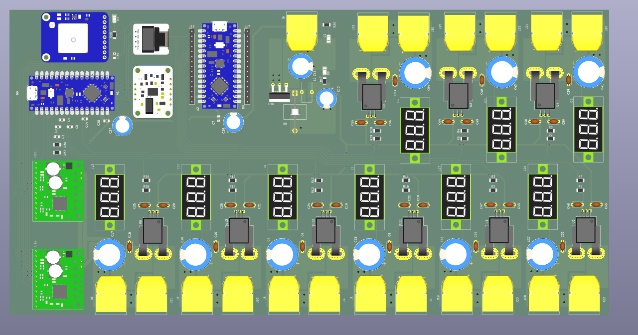
3D RENDER - TOP
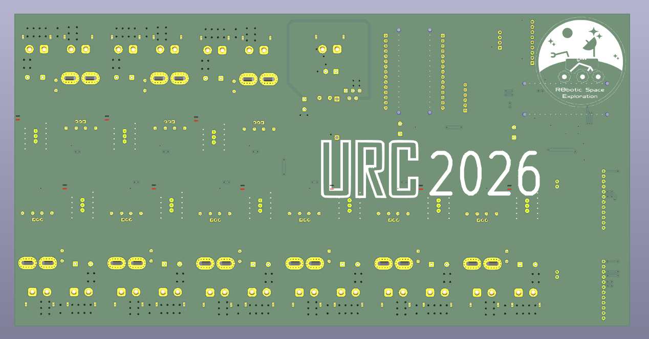
3D RENDER - BOTTOM
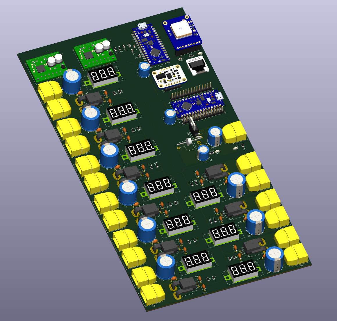
3D RENDER - TILTED
| Block | Component / Detail |
|---|
| MCU x2 | Arduino Nano ESP32 (A1, A2) |
| Stepper Drivers x2 | AMIS-30543 carrier boards (SPI, 2A per channel) |
| Current Sensors x6 | ACS758LCB-050B-PFF (±50A, Hall-effect, 40mV/A) |
| 40A Power Blocks x9 | Independent V_Estop + Motor_PWR nets per block |
| Buck Regulator | LM2596T-5V (5V / 3A output) |
| IMU | BNO055 9-axis breakout (I2C) |
| GPS | Adafruit Ultimate GPS PA1616S (UART) |
| Display | Adafruit 1.3" OLED (I2C, shared bus with IMU) |
| 40A Trace Width | 8-10mm on 2oz copper |
| Stepper Power Traces | 2mm, routed as tightly coupled parallel pairs |
Hive-1 - Autonomous Swarm Robot PCB Stack
Jan 2025 - August 2025 · 2-Layer · Autodesk Fusion 360 · All boards fabricated & functional
Three-board modular hexagonal PCB stack for Hive-1, part of the Autonomous Swarm Robots project. Each board shares a common standoff pattern and form factor, and is independently functional. Perception sensors (IMU, TOF, OLED, optical flow) are off-the-shelf breakout modules mounted via pin headers.
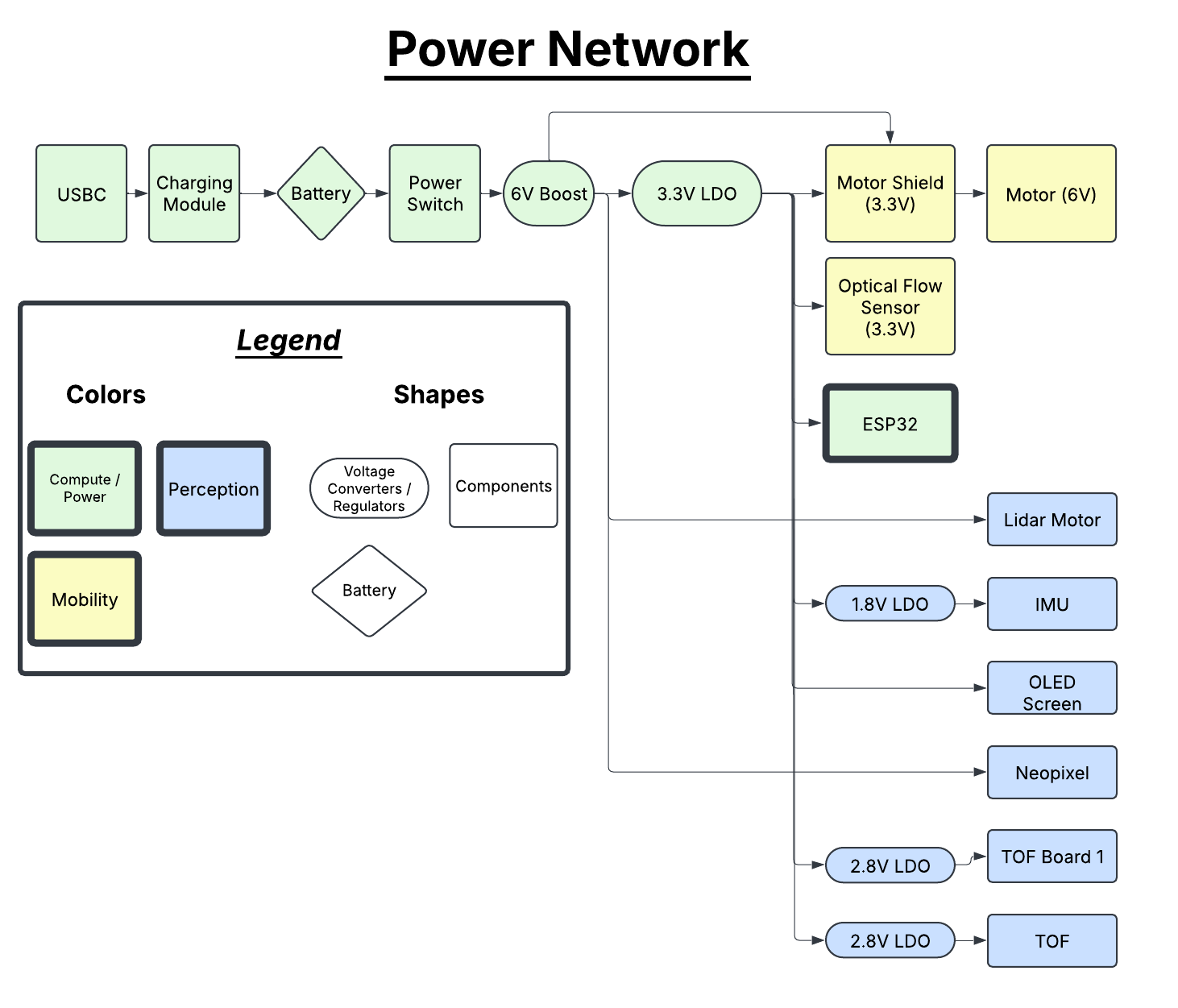
POWER NETWORK
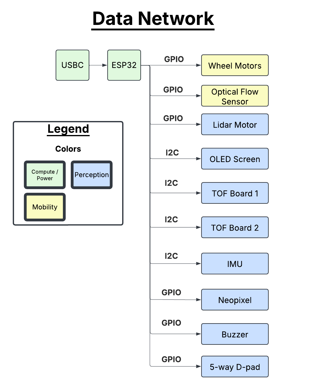
DATA NETWORK
ESP32-S3
Power Management
Li-Ion Charging
USB-C
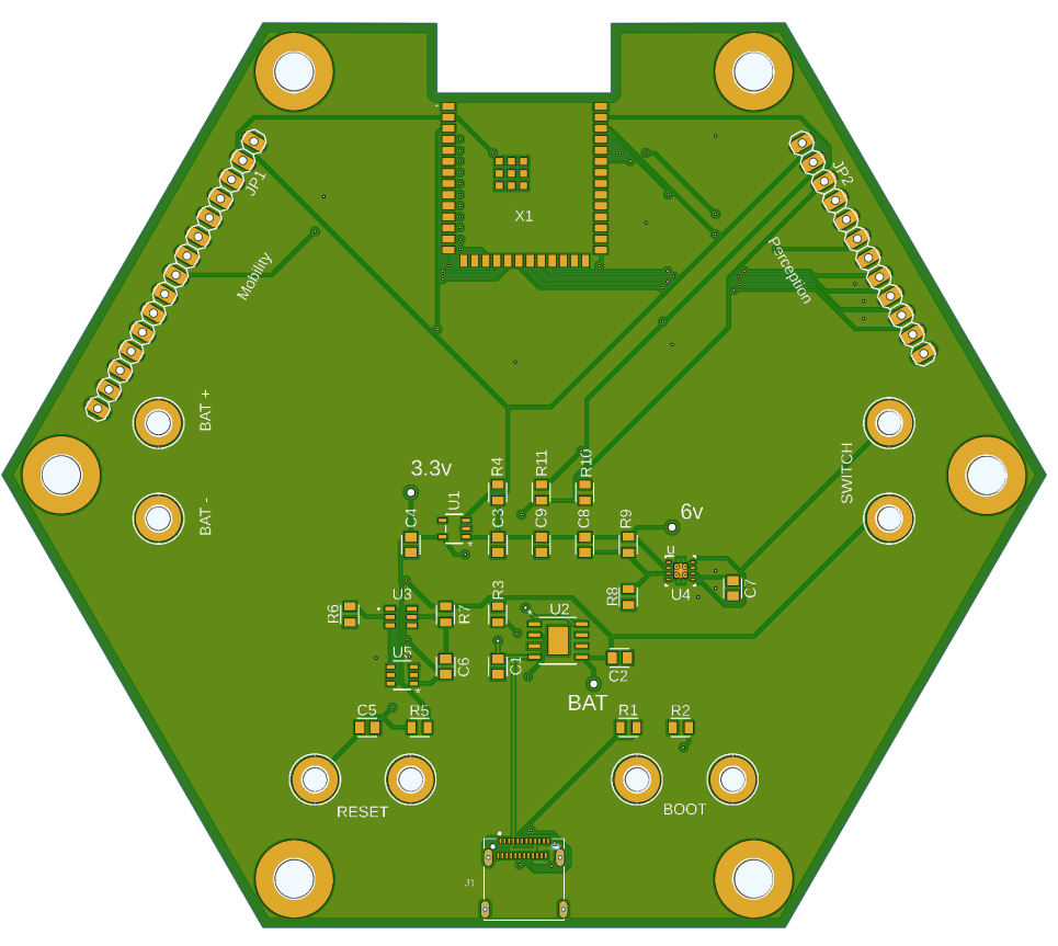
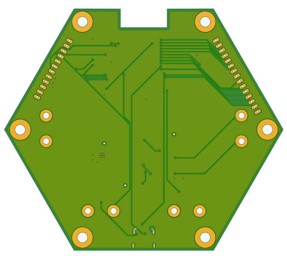
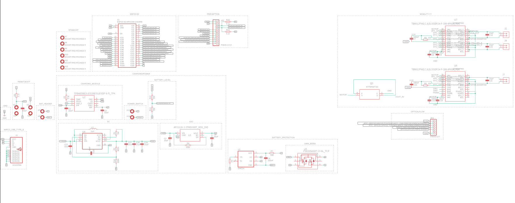
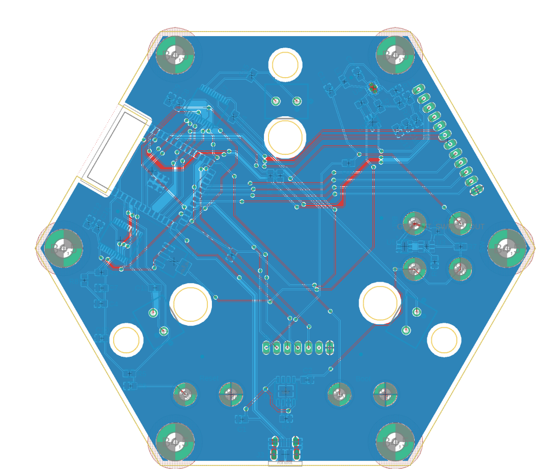
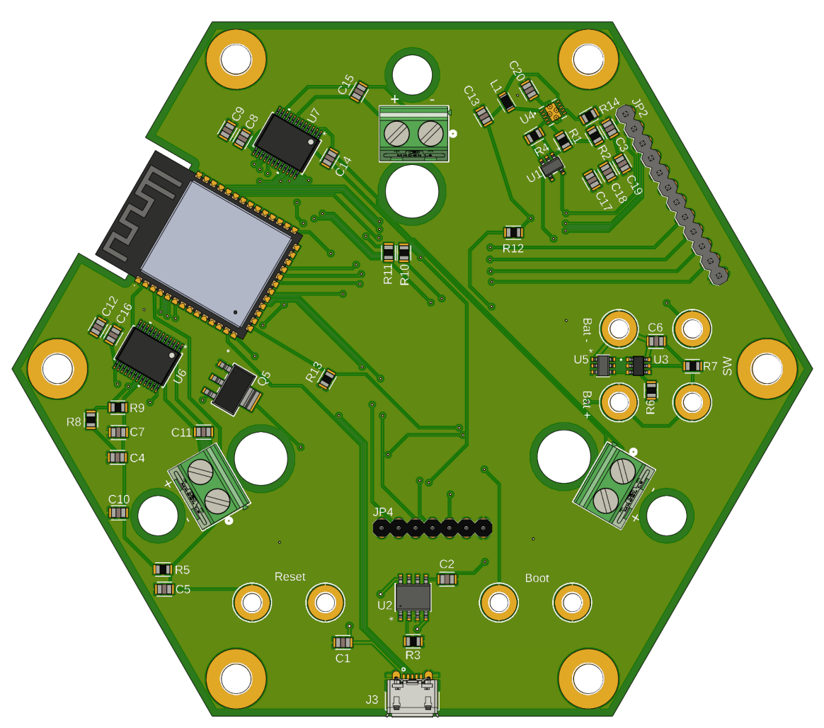
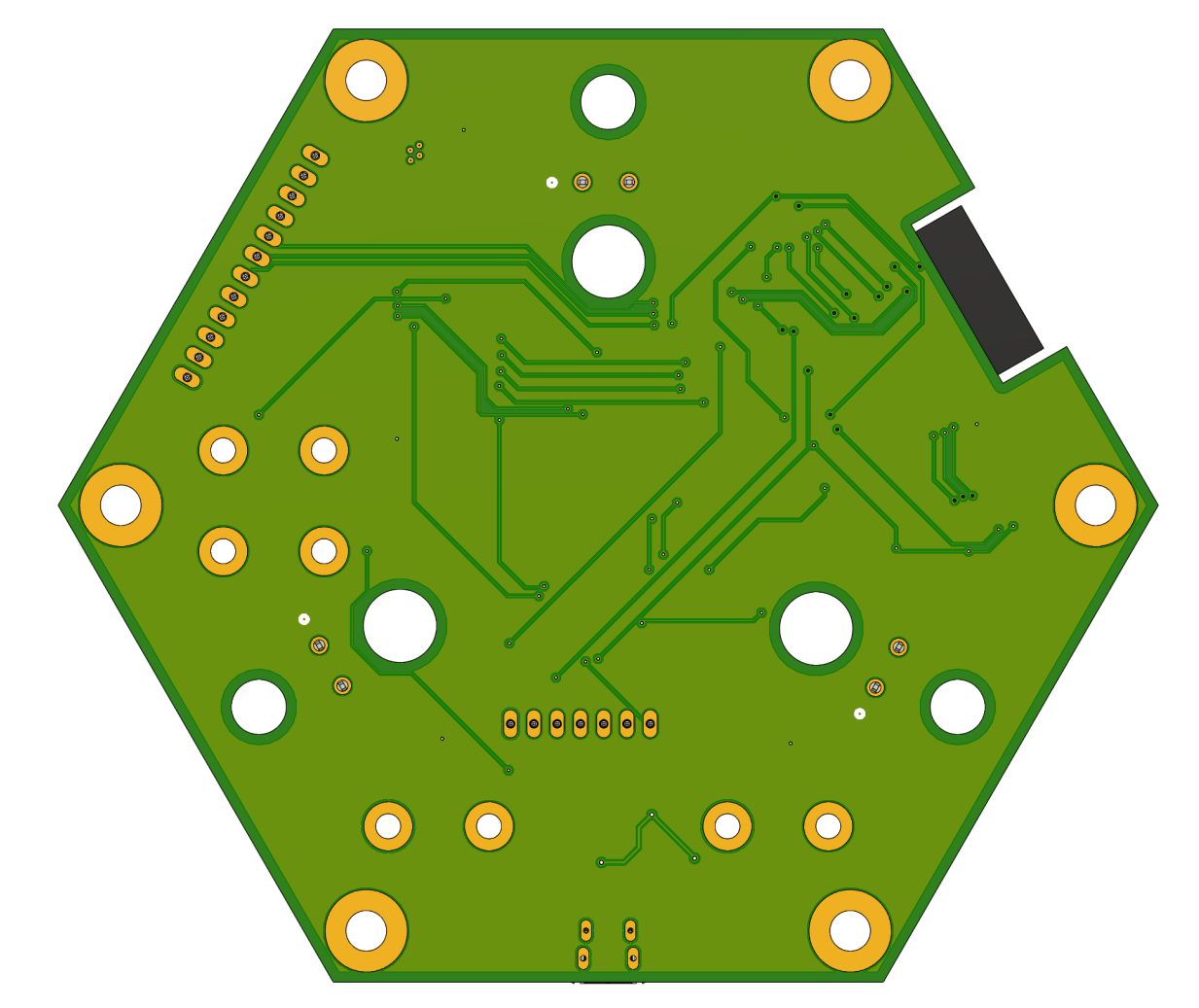
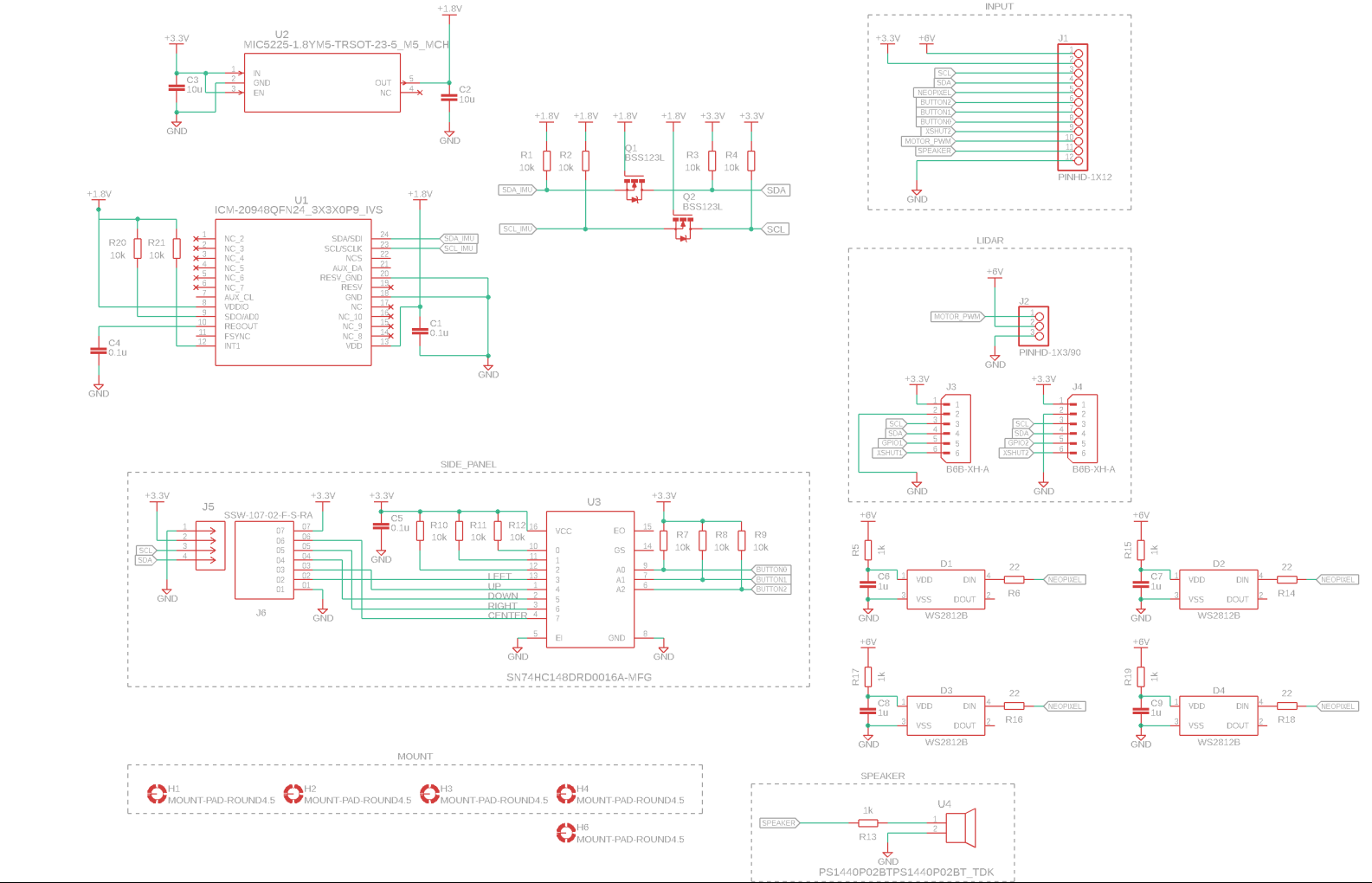
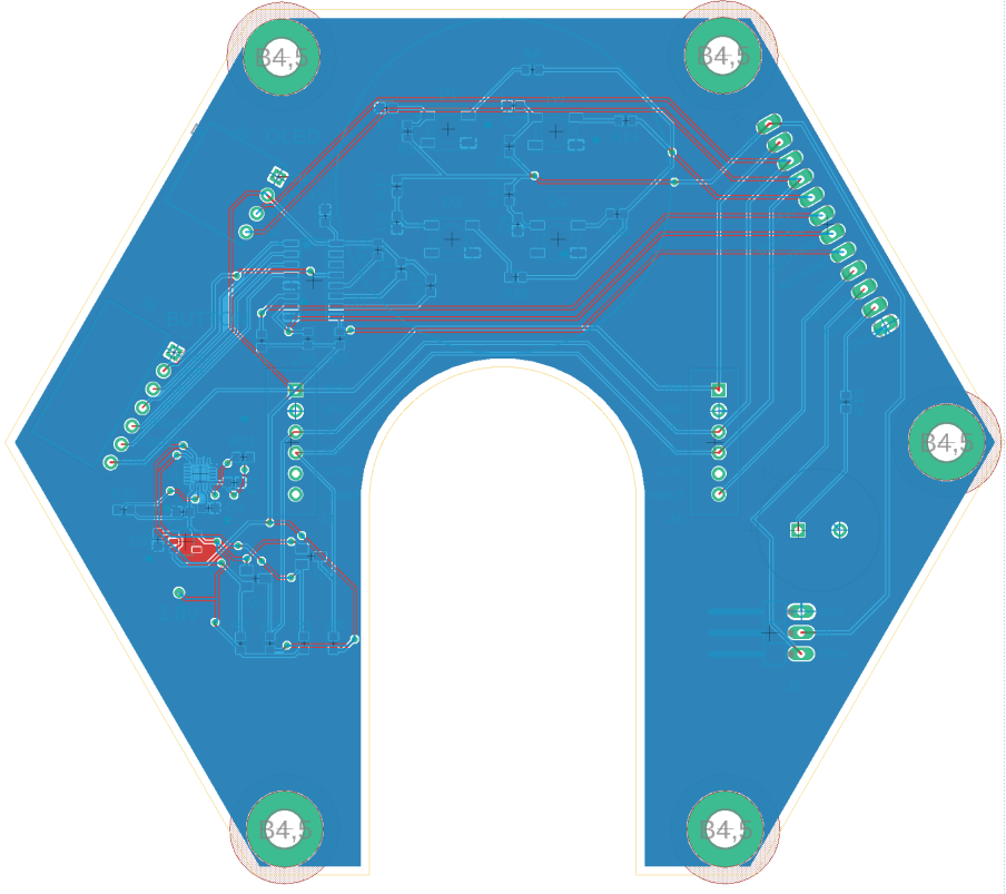
Board 1 - Compute & Power
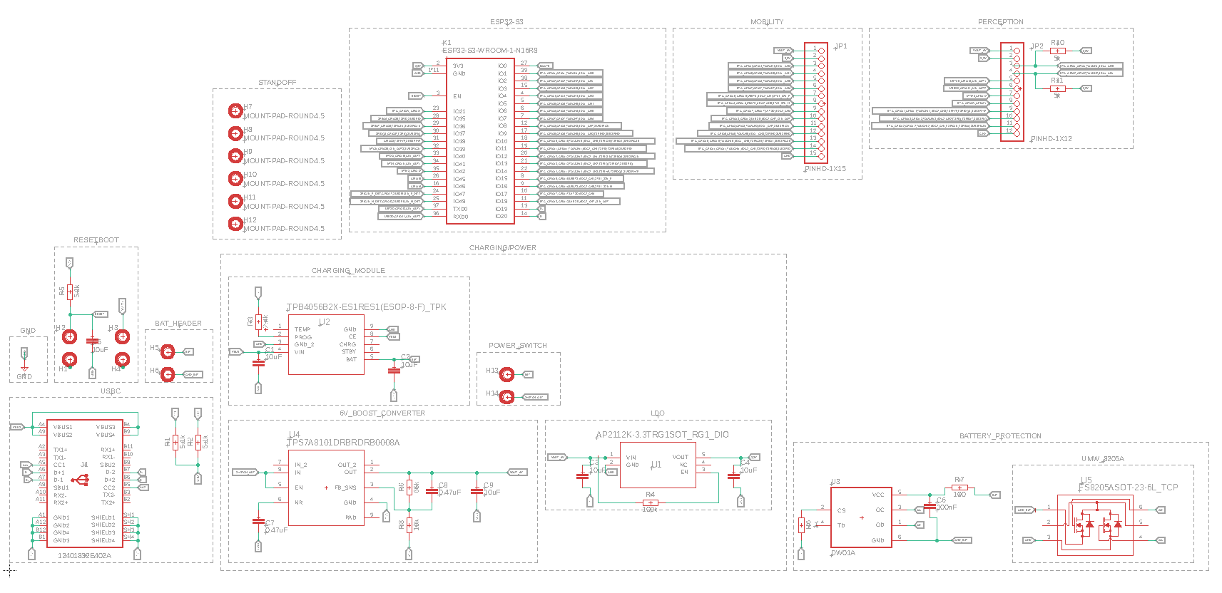
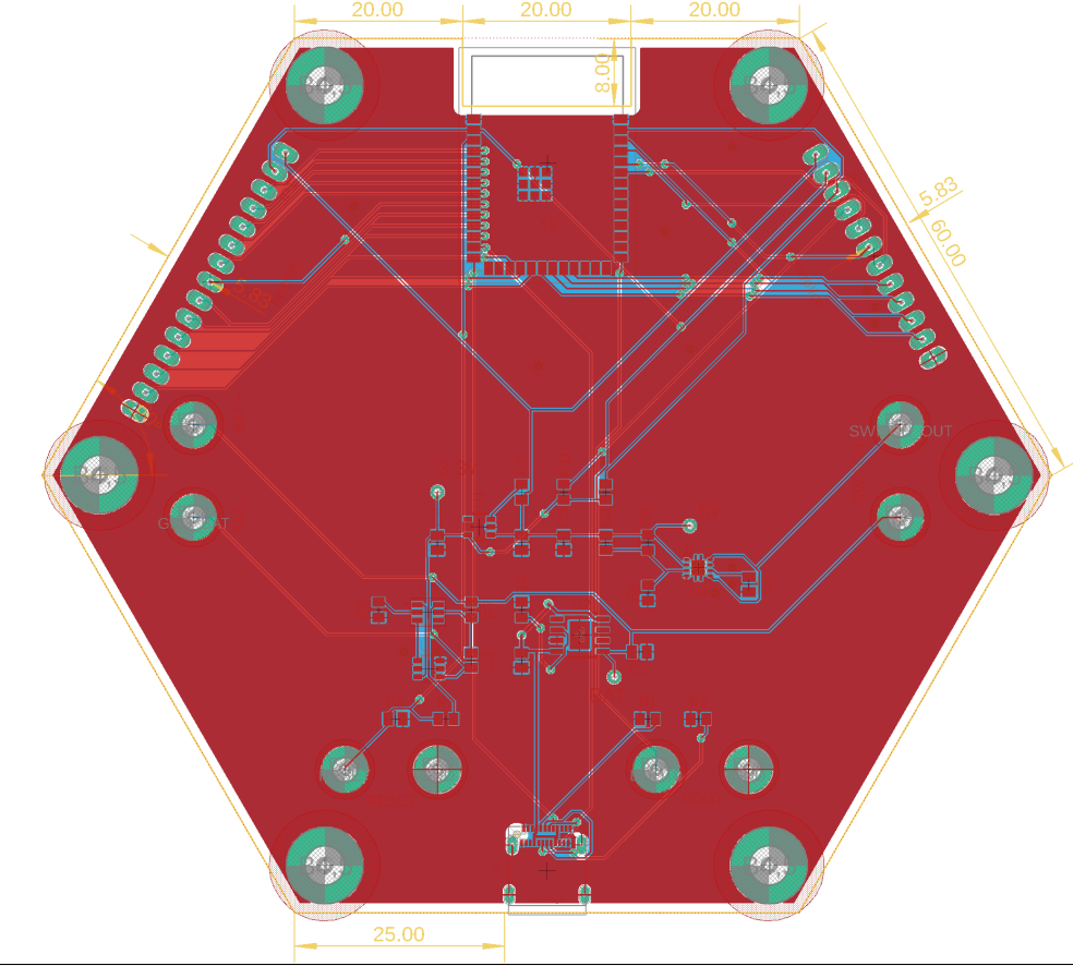
Central board handling all computation and multi-rail power delivery. Integrates a complete Li-Ion charging and protection circuit, a 6V boost converter, a 3.3V LDO, and the ESP32-S3-WROOM-1-N16R8. Exposes a 15-pin Mobility header and a 12-pin Perception header with onboard I2C pull-ups.
SCHEMATIC
PCB LAYOUT
3D RENDER - TOP
3D RENDER - BOTTOM
| Block | Component |
|---|
| MCU | ESP32-S3-WROOM-1-N16R8 |
| USB-C Connector | 12401832E402A |
| Li-Ion Charger | TPB4056B2X-ES1RES1 (ESOP-8-F) |
| Battery Protection | DW01A + FS8205ASOT-23-6L dual MOSFET |
| 3.3V LDO | AP2112K-3.3TRG1SOT |
| Mobility Header | JP1 - PINHD-1X15 |
| Perception Header | JP2 - PINHD-1X12 (5kΩ I2C pull-ups) |
TB6612FNG
Motor Control
H-Bridge
Board 2 - Mobility
Dedicated motor driver board. Receives all power and control signals from the Compute board via a 15-pin header. Drives up to four independent motor channels using two TB6612FNG dual H-bridge drivers, with a P-channel MOSFET for motor voltage switching. Motor outputs terminate at screw terminals for easy mechanical wiring.
SCHEMATIC
PCB LAYOUT
3D RENDER - TOP
3D RENDER - BOTTOM
| Block | Component |
|---|
| Motor Driver A (ch. A+B) | TB6612FNG - ELSSOP24 |
| Motor Driver B (ch. C+D) | TB6612FNG - ELSSOP24 |
| Motor Switch | NTF6P02T3G (P-channel MOSFET) |
| Interface | JP1 - PINHD-1X15 (GP2/4-11/15-18, 3.3V, GND) |
| Motor Outputs | 3x screw terminals |
| Decoupling | 100nF + 10uF per driver, 10kΩ STBY pull-ups |
Sensor Breakouts
I2C
TOF
IMU
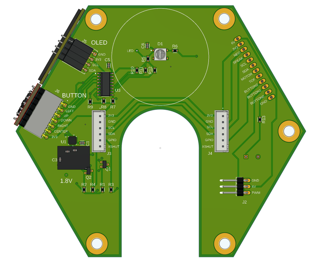
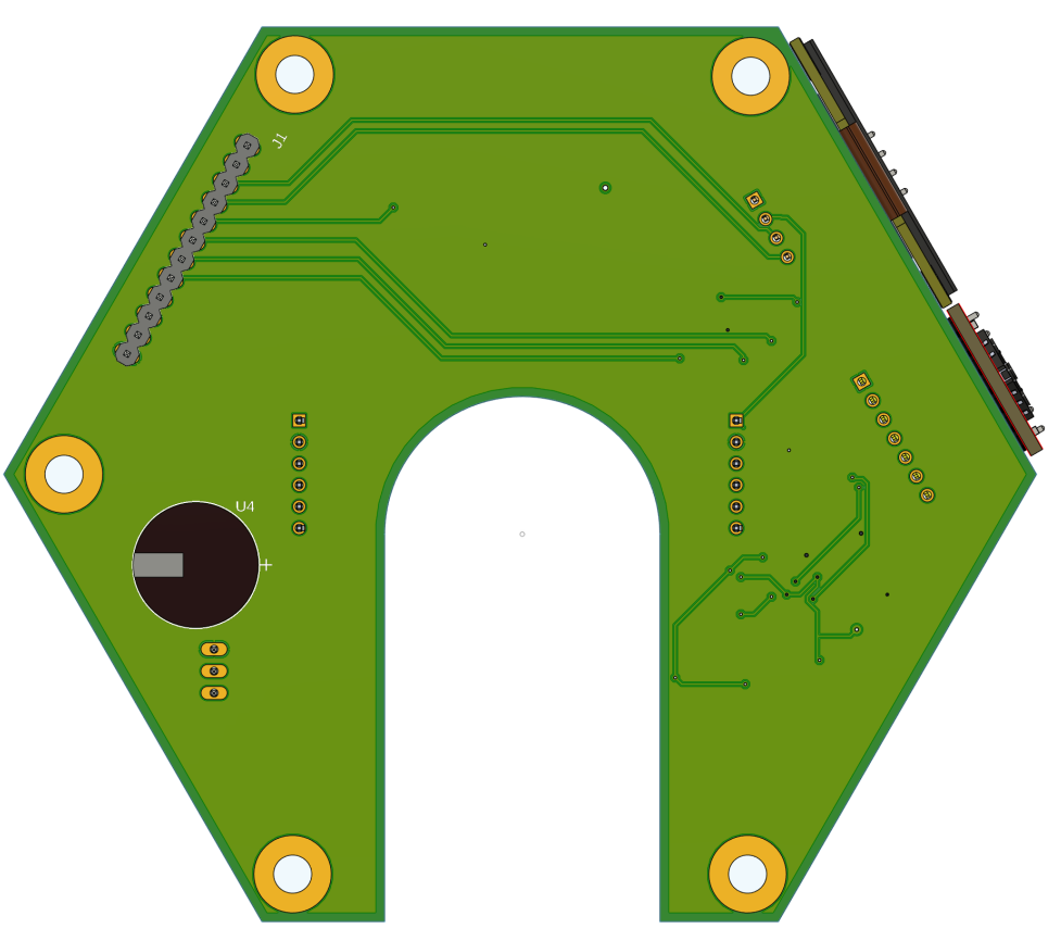
Board 3 - Perception
Perception interface board hosting breakout modules for all sensing. Connects to the Compute board via the 12-pin Perception header. Hosts I2C sensors (OLED display, 2x TOF ranging boards, IMU) and the LiDAR motor control line.
SCHEMATIC
PCB LAYOUT
3D RENDER - TOP
3D RENDER - BOTTOM
More projects coming soon.