Team RoSE - Mars Rover Avionics & Power Systems
2022-01 - Present
Robotics Mars Rover PCB Design Power Electronics ROS 2 Autonomous Systems
Team Overview
Team Robotic Space Exploration (RoSE) is a student engineering organization designing, building, and testing a fully autonomous Mars Rover for the University Rover Challenge (URC). In 2024, we advanced to the URC Finals, ranking among the top 36 teams out of 120+ universities worldwide.
To learn more, visit the official website: https://teamrosehawaii.com
Project Video
My Role - Avionics Lead
As Avionics Lead, I am responsible for the rover’s electrical and embedded systems, including:
- High-current power architecture
- Battery system engineering
- Custom PCB design
- Embedded microcontrollers
- Sensor fusion (IMU + cameras)
- ROS 2 integration
- System reliability and safety
Key Engineering Contributions
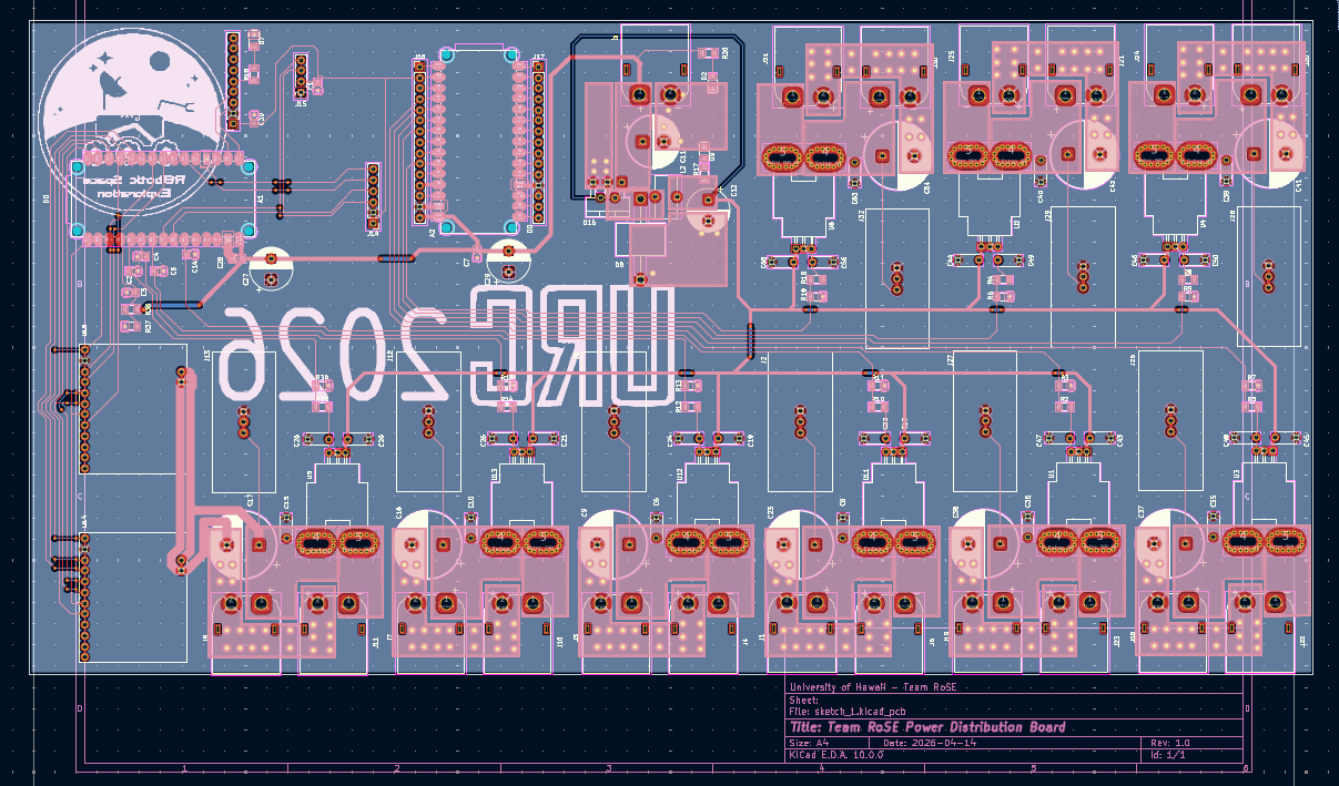
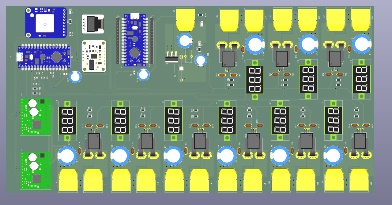
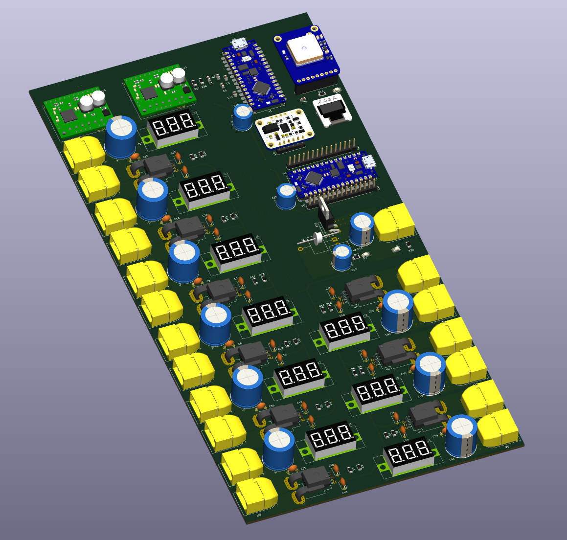
1. Custom Rover Motherboard - Motor Control System Board (2024-2025 Build)
A 2-layer professional-grade motor control PCB designed in KiCad 10. The board integrates high-current power management, stepper motor control, sensor fusion, GPS navigation, and dual microcontroller architecture into a single board.
Board specs: 2-layer, 1.6mm FR4, 2oz copper both layers, pink soldermask, white silkscreen
Architecture:
- Dual Arduino Nano ESP32 microcontrollers (A1, A2) - central signal routing hub
- 9x independent 40A power monitoring blocks, each with dedicated V_Estop and Motor_PWR nets and ACS758 current sensing
- 2x AMIS-30543 stepper motor driver carrier boards (SPI, up to 2A per channel)
- LM2596T-5V buck regulator (5V/3A output) with strict switching loop layout
- 6x ACS758LCB-050B-PFF Hall-effect current sensors (±50A bidirectional, 40mV/A)
- BNO055 9-axis IMU breakout (I2C)
- Adafruit Ultimate GPS Breakout PA1616S (UART)
- 1.3” OLED display (I2C, shared bus with IMU)
Design highlights:
- Single unified GND plane on B.Cu; top layer handles signal routing + power traces + partial GND pour with stitching vias every 10-15mm
- 40A power traces: 8-10mm wide on 2oz copper; stepper power pairs: 2mm
- EMI management: stepper V_Estop/Motor_PWR routed as tightly coupled parallel pairs for field cancellation; SPI lines routed perpendicular to power traces at every crossing
- Decoupling per IC: 100nF X7R ceramic closest to VIN pin, 100µF bulk cap behind it; 100nF analog filter caps on ESP32 ADC input pins
- Custom netclass ‘40A_Power’ with 0.5mm clearance; footprint-level pad clearance override for ACS758 (0.4mm) applied at library level
- DRC clean: 0 errors, 0 warnings at final check
Purpose: simplify wiring, improve reliability, and centralize rover electronics into a single maintainable board.
2. High-Current Power System
- Designed the DC power stage for four regulated 12 V / 7 A rails
- Integrated IC-based battery-level and voltage monitoring
- Implemented overcurrent protection with fused outputs
- Engineered modular harnesses for rapid field servicing
Result: Stable power delivery during high-load terrain traversal & drive motor stalls.
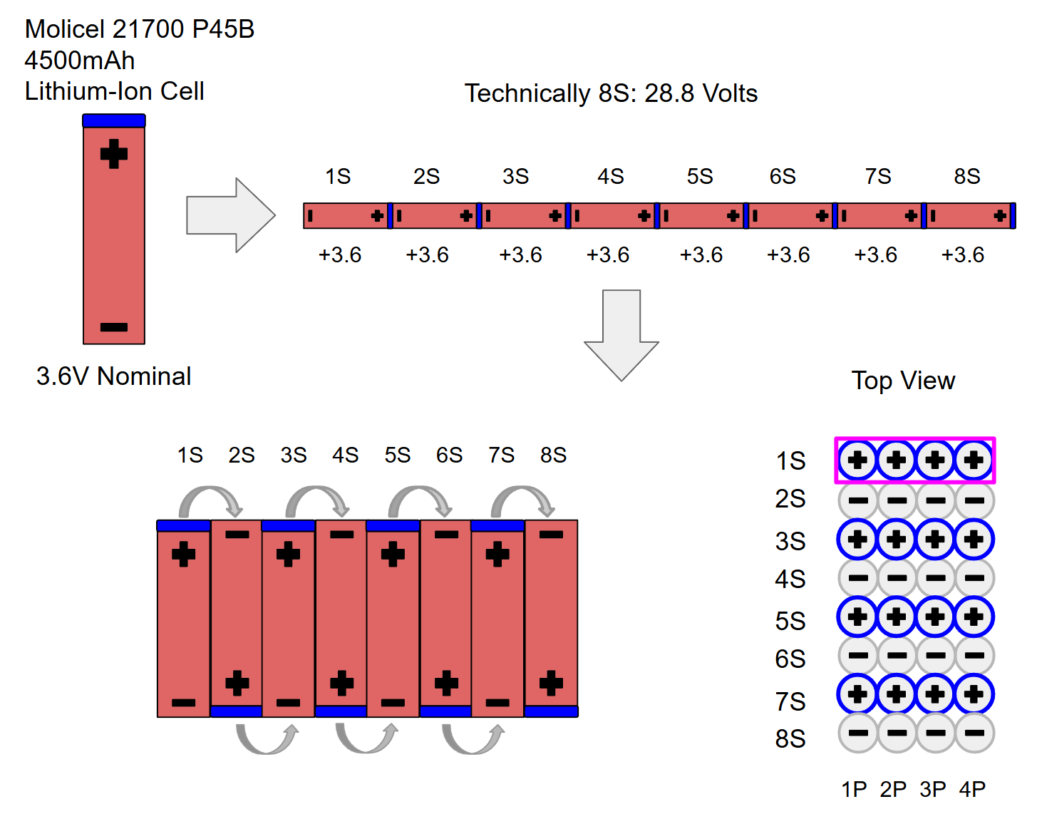
3. 8S-4P Li-ion Battery Pack (530 Wh)
- Custom-designed 8S-4P 21700 Li-ion pack
- Integrated Battery Management System (BMS) for protection & balancing
- Provides ~30V nominal, 530 Wh, and 3+ hours of runtime
- Tested under URC-level current spikes and environmental stress
4. Sensor Fusion & ROS 2 Navigation Integration
- Integrated IMU and vision modules for improved localization
- Contributed to integrate ROS 2 pipelines for navigation
- Enabled autonomy required for the Autonomous Navigation Mission
Result: Robust localization in rough outdoor terrain.
Materials & Methods
Electrical Architecture
- Custom PCBs for battery protection, distribution, and regulation
- High-current wiring, fusing, and connectorization
- Jetson Xavier compute integration
- Modular harnesses for rapid assembly and field repairs
Results
- Rover achieved 3+ hour runtimes during field missions
- Successfully completed URC 2024 missions, ranking in the top 36 globally
- Improved wiring reliability through modular connectors & shortened harness paths
- Achieved consistent performance during URC practice missions
Future Work
- Next-generation high-discharge battery pack
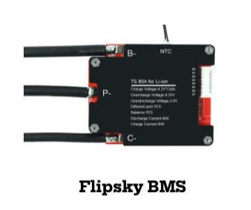
- Integration of Flipsky BMS
- Breakout PCBs for arm & payload subsystems
- Full avionics integration for URC 2025 competition rover
Conclusion
Guided by results from the 2024 URC Finals, we are building an entirely new electrical and embedded architecture for the 2025 rover - designed for higher reliability, better autonomy performance, improved modularity, and maintainability. Major subsystems are nearing completion, with full-system testing beginning next semester.
Acknowledgements
- UH College of Engineering
- SOEST, HSFL, HIGP
- UROP Program
- Faculty Advisors
- Protocase
- Team RoSE alumni and supporters